An ODM lighting project can pass engineering sign-off and still fail before production builds a single unit. This ODM lighting quality audit focuses on the release window between sign-off and production.
Key Takeaways
- Engineering sign-off does not by itself confirm that the production configuration matches the validated sample.
- Every post-sign-off change needs a change order, an impact assessment, and a defined retest scope.
- Before production release, buyers should verify configuration-specific LM-79, ISTMT, TM-21, and change-control evidence.
1. Why projects fail after sign-off, not before
The stretch of time between sign-off and release is where the risk concentrates. A driver gets substituted because the original is on backorder. A gasket compound changes because a supplier discontinued a formulation. A heatsink gains two millimetres so the housing fits a new mould. Each change is small. None of them automatically reopens the test plan.
Buyers often read sign-off as the end of technical risk. It marks something narrower: the design, as it stood on that date, met its requirements under test conditions. The release window remains vulnerable when component and process changes do not trigger the relevant retesting.
For a specifier or an integrator acting as the technical reviewer, the controlling question changes at this point. The issue is whether the product about to enter production is still the product that passed validation. This guide sets out six recurring failure modes in that release window. Review ANOVA's engineering capability for the wider development and validation context.
2. The release gate concept
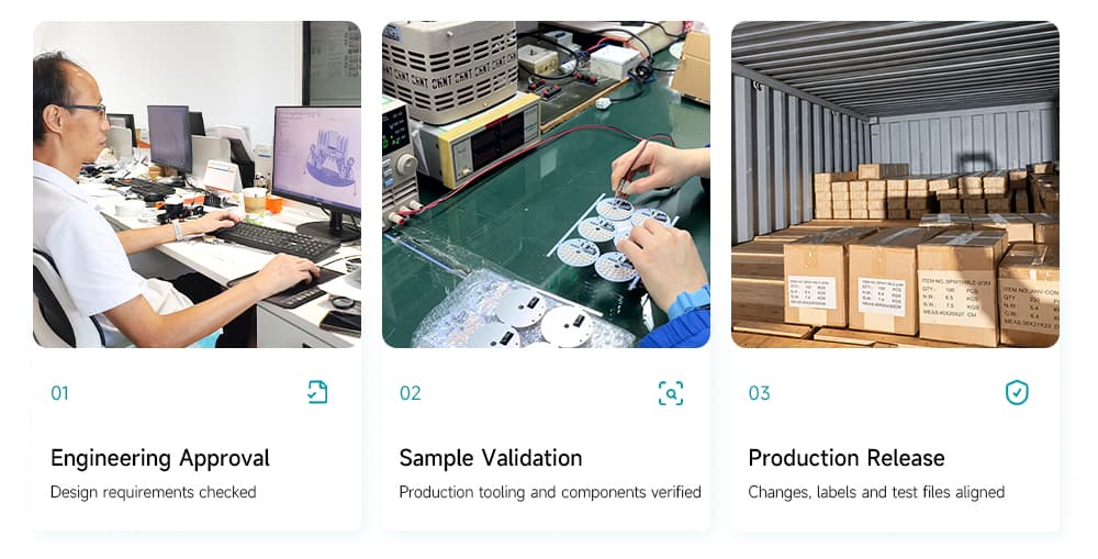
A release gate is a control point that a project must clear before it moves to the next stage. In an ODM lighting program, the gate has three checkpoints: engineering approval, sample validation, and production release. Each checkpoint exists to stop a different class of problem.
Engineering approval confirms that the design meets the specified photometric, thermal, and sealing requirements under test conditions. Sample validation confirms that pilot units built with production tooling and production components behave the same way the engineering samples did. Production release confirms that nothing changed between sample validation and the first production run, and that certificates, labels, and test files describe the units actually being built.
A release gate in an ODM lighting project has three checkpoints, engineering approval, sample validation, and production release, and each checkpoint blocks a different class of defect from reaching the next stage.
Failure modes tend to appear in the transitions. A change approved at one checkpoint reaches the next checkpoint without anyone rerunning the relevant test. The gate works only when every change is logged and mapped to a retest scope.
3. Six failure modes
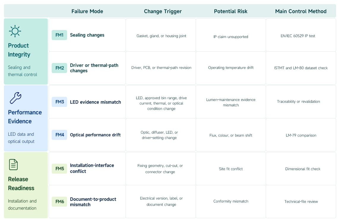
ANOVA does not publish annual failure-frequency data by mode. The sections below therefore state the release criteria and evidence required for each change class.
FM1. Sealing changes leave the IP claim unsupported
A gasket substitution, revised groove, or changed cable entry can alter a sealing interface. The outside appearance may remain unchanged while compression or assembly consistency differs.
An IP test result for an earlier enclosure configuration does not automatically establish the same protection for a revised sealing interface.
Review the changed interface against the tested assembly. Where the change affects protection, validate the revised configuration using the applicable EN/IEC 60529 IP tests (IEC 60529:2013). See the IEC 60529 IP Code. Record the sample revision and assembly conditions so the result can be traced to production.
Acceptance should reference the required IP classification and applicable test criteria. A visual inspection alone leaves ingress performance unverified. Include the relevant assembly specification in the release package.
FM2. Driver or thermal-path changes alter operating temperatures
A replacement driver can change LED operating current. A housing revision or altered thermal interface can change heat transfer. Either change requires assessment before earlier thermal evidence is reused.
ISTMT measures temperature within the assembled lighting product under defined operating conditions, providing evidence for assessing whether the installed light source operates within the conditions supporting its lumen-maintenance evaluation. See the ENERGY STAR laboratory guide.
Repeat relevant thermal measurements on the revised configuration. Review the LED temperature and current against applicable ANSI/IES LM-80-21 evidence, and assess the driver against its own operating limits. LM-80 does not establish driver reliability.
Record mounting conditions and ambient temperature alongside the readings.
FM3. Lumen-maintenance evidence does not cover the installed LED
An LED substitution can leave a project using an ANSI/IES LM-80-21 report or ANSI/IES TM-21-21 projection that belongs to a different light source. Similar initial output does not establish equivalent long-term behavior.
ANSI/IES TM-21-21 projects LED lumen maintenance from ANSI/IES LM-80-21 data; applying that projection to a luminaire requires checking the installed light-source identity and relevant operating conditions. See the IES position on LED lifetime prediction.
Trace the production LED to the component identification covered by the supporting data. A different production lot needs traceability; it does not automatically require a new LM-80 test.
Check the projection inputs against measured operating conditions. Record the basis for accepting the evidence, especially after a substitution.
FM4. Optical performance drifts from the approved sample
A revised optic, different LED selection, or changed driver setting can alter the lighting result. The production configuration may retain the same nominal description while differing from the approved sample.
ANSI/IES LM-79-24 provides measurement methods for optical and electrical performance; release acceptance also requires project-defined criteria for the measured results. See the official LM-79-24 standard page.
Compare the revised configuration with the approved baseline using relevant LM-79 measurements. Review luminous flux and color temperature, together with light distribution and beam angle where specified.
Record consistent operating conditions for the comparison. “Looks similar” leaves a technical reviewer without a measurable basis for acceptance.
FM5. The installation interface conflicts with site conditions
A fitting can satisfy its optical requirements and still fail the installation review. Revised fixing geometry may conflict with the available opening. A connector change may reduce wiring clearance or prevent the intended connection.
Installation compatibility requires agreement between the released mechanical and electrical interfaces and the documented site conditions.
Check the revised assembly against controlled installation drawings and the actual interface requirements. Use a representative fit check where drawings cannot resolve clearance or access.
Record the opening dimensions, fixing arrangement, and connection details used for acceptance. If site conditions remain unknown, retain the issue as an open release condition. An assumed dimension should not become an approved requirement.
FM6. Documents describe a different product
A revised electrical version can reach production while an earlier label or declaration remains in the release package. The documents may appear complete even though their product identification no longer matches the assembly.
CE/UKCA conformity documentation must identify and support the applicable product configuration; a marking alone cannot establish document-to-product consistency. See the UK government conformity documentation guidance. For Australia or New Zealand projects, confirm the applicable RCM requirements. For Gulf or Saudi projects, confirm the country-specific conformity route, including G-Mark or SASO where applicable.
Compare a representative unit with the controlled bill of materials and electrical specification. Then check its model identification, rating label, and relevant conformity documents for consistency.
Resolve differences before release. The review should establish which evidence covers the revised configuration and which documents require updates.
4. Validation criteria table
Every post-sign-off change in an ODM lighting project maps to a minimum retest scope, and the release gate holds the change until that scope is completed and signed.
The matrix below states the minimum retest scope for the six failure-mode change classes; the deciding responsibility column names who rules on the result.
The gate rule is simple: no change crosses into production without its row in this table closed. Buyers reviewing a supplier's process should ask to see the change log alongside the test records, because the log shows whether the rule holds in practice.
| Change item | Risk | Minimum re-validation | Deciding responsibility |
|---|---|---|---|
| Gasket, gland, or housing joint | IP rating void (FM1) | EN 60529 IP test on the changed configuration | ANOVA test lab, with QA sign-off |
| Driver model or PCB revision | Thermal drift, maintenance data invalid (FM2, FM3) | ISTMT plus ANSI/IES LM-80-21 dataset match check | ANOVA thermal engineer |
| LED batch or bin | Photometric and maintenance drift (FM3, FM4) | Traceability check; revalidate if LED, approved bin range, drive current, thermal, or optical conditions change | ANOVA optical lab, with thermal review as required |
| Optic or diffuser source | Beam angle and flux shift (FM4) | LM-79 photometric comparison against the golden sample | ANOVA optical lab |
| Fixing geometry or cut-out | Site installation conflict (FM5) | Dimensional check against approved installation drawings | ANOVA mechanical engineer, with project confirmation |
| Electrical version or label content | Certification mismatch (FM6) | Technical file review against the production configuration | ANOVA compliance owner |
5. What buyers should request
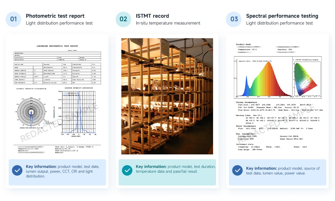
You need evidence that the tests ran and that the results belong to the product you are buying. A buyer reviewing an ODM lighting supplier should request four records before production release: a redacted LM-79 report, the ISTMT record, the TM-21 projection tied to the LED batch, and the change order log.
The LM-79 report documents flux, efficacy, colour temperature, and colour rendering for a complete luminaire, which tells you the photometric baseline. The ISTMT record shows the measured solder-point temperature inside the finished housing rather than a calculation, which tells you the thermal baseline. The TM-21 projection connects the quoted service life to the LM-80 dataset of the actual LED in the product. The change order log shows whether every change cleared its retest scope. ANOVA's engineering checklist for the release gate is available in limited numbers for projects entering the production stage this quarter.
Send ANOVA your change list and installation conditions. Within 3 working days, our engineering team will map each open change to its required release-gate scope.
7. Next step
If your project is between sign-off and production, send ANOVA your change list and installation conditions and request a release-scope review. Within 3 working days, the engineering team provides a release-scope mapping for each open change and confirms what the gate requires before the first production run. Email qijing.li@anovalighting.com or use the enquiry form on the site. For background, read how the ODM lighting development process is structured, what the testing and validation workflow covers, and how the release gate applies in project segments such as hotel lighting.
FAQ
Can the design still change after sign-off?
Yes, and changes are normal in an ODM program. The risk is an unlogged change. Every post-sign-off change should enter a change order, carry a retest scope, and clear the release gate before production.
Which changes require retesting?
Any change to sealing parts, driver, LED type or approved bin range, optics, or mechanical interface. For a normal lot of the same approved LED, traceability is required; repeat testing is required only when the change affects the supporting evidence or operating conditions.
Do LM-79 and TM-21 reports need to be current?
They need to match the shipped configuration. An older report covering an identical configuration remains valid. A recent report covering a changed configuration does not help you.
What is ISTMT?
In-situ temperature measurement test. It records the actual temperature at the LED solder point and at critical driver components inside the finished luminaire under operating conditions. The result decides whether the LM-80 dataset used for the TM-21 projection still applies to the product as built.
How do I confirm the documents match the physical product?
Compare the electrical revision on the label and in the test reports with the technical file, and ask the supplier for the change order log. Consistent revision references across all three sources are the evidence you want.
Who signs off before release?
At ANOVA, release requires sign-off from the test lab covering photometric and sealing results, the thermal engineer covering ISTMT and the LM-80 match, and the compliance owner covering certificates and labels. The production plan starts only after all three sign.