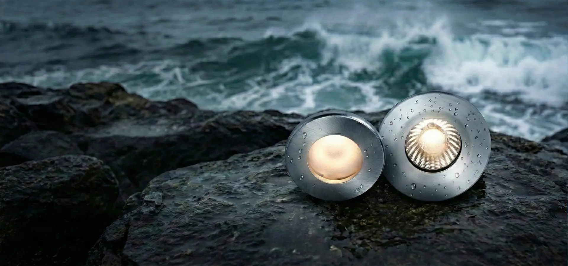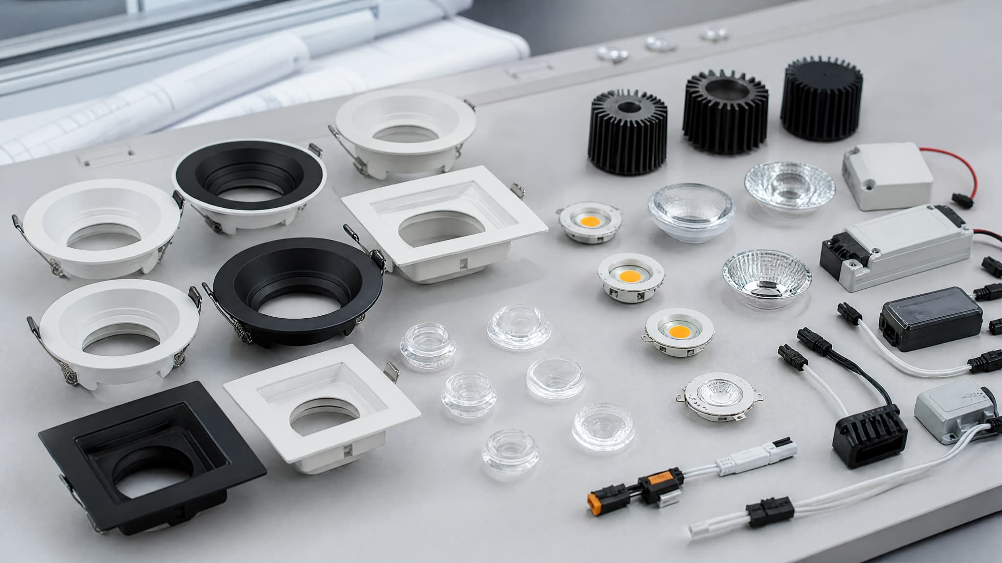
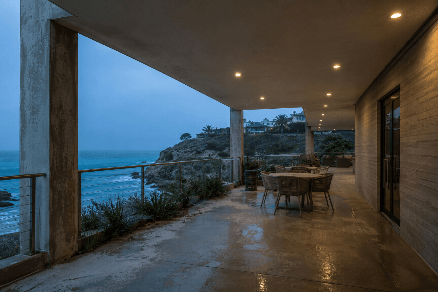
Coastal lighting design begins with the exposure profile rather than a generic corrosion-resistant product label. Humid salt air, direct spray, cleaning chemicals, temperature changes and trapped water can affect the housing, coating, fasteners, sealing faces, cable entries and drainage paths in different ways. A stainless-steel trim or an IP rating may address one part of the risk, but neither describes the reliability of the complete luminaire assembly.
A corrosive-environment luminaire design therefore coordinates material selection, surface protection, sealing, fastener interfaces, drainage, thermal management and validation around the actual installation. The engineering goal is to define a controlled configuration for the intended coastal or salt-exposed application—not to make a universal corrosion-proof claim. For a broader overview of corrosion mechanisms and protection methods, start with the Corrosion-Resistant LED Lighting guide.
Why Coastal and Corrosive Environments Change Luminaire Design
Corrosion begins when a vulnerable material, an electrolyte and an electrochemical path meet. Humidity can leave a thin conductive film; salt makes that film more aggressive and can remain after visible water has evaporated. Chemicals from cleaning, industrial processes or swimming-pool areas may attack metals, coatings, elastomers or connectors in different ways.
Temperature changes can pull humid air through joints or create condensation inside an enclosure. Water ingress can then remain around screw recesses, cable entries and horizontal interfaces. Once a coating is scratched, thin at an edge or separated from its pretreatment layer, corrosion can spread beneath the finish rather than remaining a cosmetic surface mark.
- Humidity: creates persistent moisture films and condensation at cool surfaces.
- Salt: increases conductivity and accumulates in crevices, fasteners and drainage paths.
- Chemicals: may attack metal, coating, seal or connector materials.
- Galvanic corrosion: can occur where dissimilar metals are electrically connected in moisture.
- Damaged coatings: expose the substrate at edges, holes, scratches and tool-contact points.
- Water ingress: carries contaminants into joints and can keep internal interfaces wet.
1. Select Coastal Luminaire Materials Based on Exposure
Material selection should start with the actual exposure, not a universal ranking. Direct salt spray, humid air, periodic washing, chemical contact, immersion risk, UV, impact, heat and maintenance access can lead to different choices. Cost, manufacturability, appearance, electrical insulation and compatibility with adjacent parts also matter.
A 316L option may be appropriate for selected components in some chloride-exposed applications, but its name alone does not make the complete luminaire corrosion proof. Crevices, deposits, surface contamination, dissimilar fasteners and cleaning conditions still have to be considered.
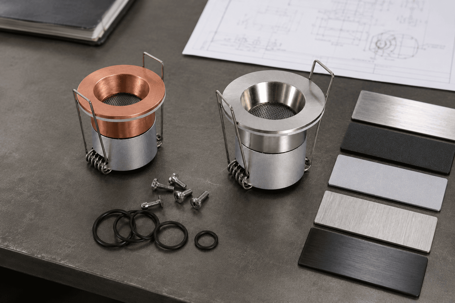
| Material option | Engineering role | Conditions to review |
|---|---|---|
| Aluminum | Lightweight housing and useful thermal path | Alloy, pretreatment, finish, cut edges and fastener interfaces |
| Stainless steel | Exposed trims, fasteners or structural parts | Grade, finish, fabrication, crevices and contact with other metals |
| 316L option | Selected parts for some chloride-exposed conditions | Exact exposure, deposits, fabrication and maintenance |
| Coated metal | Combines substrate function with a protective barrier | Pretreatment, continuity, edge coverage, curing and damage |
| Engineering plastics | Electrical isolation, covers or non-corroding components | UV, temperature, chemicals, movement and long-term sealing pressure |
For examples of how exposure conditions shape project requirements, review our coastal and high-humidity application experience.
2. Protect the Surface
Surface protection is a controlled process rather than a color specification. Cleaning and pretreatment affect adhesion; anodizing changes the aluminum surface; powder coating creates a barrier; and other protective coatings may be used where the substrate, geometry and environment support them. The selected system must remain compatible with seals, adhesives, fasteners and assembly temperatures.
Coating thickness is useful only when it is accompanied by consistency and coverage. Sharp edges, deep recesses, threads, machined faces and screw holes can receive less protection than flat panels. Inspection should therefore focus on the difficult geometry, not only the most visible face of a sample.
- Define the substrate preparation and pretreatment before the decorative finish.
- Review anodizing or powder coating against the alloy, appearance and exposure conditions.
- Protect machined areas and interfaces that are created after the main coating process.
- Check coating continuity, edge coverage, curing and handling damage on approved samples.
- Specify how scratches or damaged surfaces are controlled during assembly and installation.
Share the exposure, installation, cleaning, moisture and maintenance conditions so the main corrosion risks can be reviewed before a product configuration is defined.
3. Design Sealing and Drainage as One System
A sealing system must control every realistic moisture path. An O-ring or gasket works only when its material, groove, compression, mating surfaces and assembly are coordinated. Housing stiffness and fastener spacing influence whether compression remains even around the joint. Reopening a serviceable fitting also creates a requirement to inspect, clean and correctly reseat the seal.
Cable entries and connectors deserve the same attention as the main housing. Cable diameter must match the gland range, strain should not disturb the seal, and field joints need protection suitable for their actual location. Housing joints should avoid capillary paths and water traps. Where water cannot be completely excluded, drainage must move it away without creating a new ingress route.
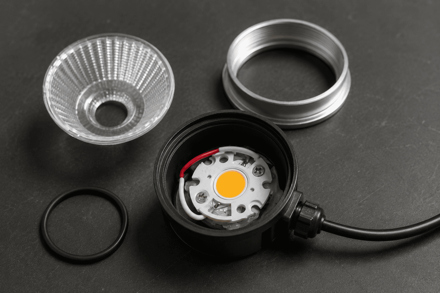
- O-ring: review groove geometry, material, compression, cleanliness and assembly control.
- Gasket: review contact width, compression uniformity, aging and replacement requirements.
- Cable entry: match the cable, gland, bend radius, strain relief and mounting direction.
- Connector: review locking, sealing, material, field assembly and protected location.
- Housing joints: control tolerances, screw loading, capillary paths and service access.
- Drainage: prevent standing water while maintaining the intended protection strategy.
4. Control Fasteners and Dissimilar-Metal Interfaces
Screws, washers, brackets and housing joints often show the first visible corrosion because they combine exposed edges, high local stress, tool damage and small crevices that retain moisture. Threads may remove a coating during installation, while a recessed screw head can collect water and salt. Replacement fasteners can introduce another metal or an unprotected finish that was not part of the approved design.
Dissimilar metals add a galvanic risk when they are electrically connected and wet. The severity depends on the material pair, relative exposed areas, electrolyte and duration of wetness. Practical controls can include compatible fastener selection, isolation washers or barriers, continuous coating, protected recesses and drainage. Joint torque must also be controlled: too little can leave a moisture path, while too much can distort the housing or gasket.
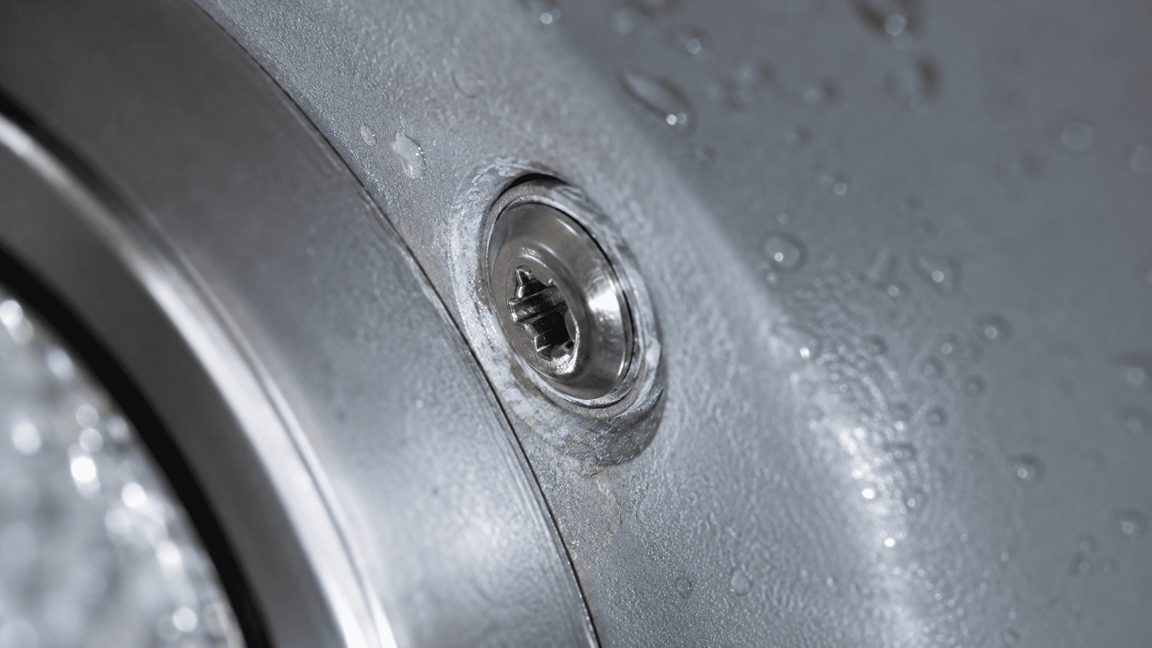
- Record the approved fastener grade, finish, washer and replacement specification.
- Review electrical contact between dissimilar metals and add isolation where appropriate.
- Avoid recesses and horizontal interfaces that retain water or salt deposits.
- Control tightening so the joint is sealed without deforming its components.
5. Manage Heat Without Compromising Protection
Water protection and thermal management can pull the design in different directions. A closed enclosure helps limit direct moisture paths, yet it also reduces air exchange and can trap heat around the LED and driver. Potting or conformal protection may protect selected electronics but can change heat flow, component stress and serviceability.
The thermal path should be developed through the LED board, interface materials, housing and surrounding installation space without relying on an opening that weakens the sealing concept. Driver placement, housing mass, surface area, ceiling insulation and ambient temperature should be reviewed as one system. Thermal validation should use the approved mechanical and sealing configuration because changing a gasket, coating, potting material or driver location can change the result.
6. Validate the Coastal Lighting Design Before Production
Validation should follow the identified failure modes and the approved product configuration. A material coupon can help compare finishes, but it does not represent fasteners, seals, cable entries, assembly tolerances or electrical function in a complete luminaire. Test plans should identify the sample, method, exposure, inspection criteria and any functional checks before and after the test.
Salt-spray exposure can reveal weaknesses in coatings, fasteners and interfaces, but test hours are not a direct prediction of service life. IP testing examines defined dust and water ingress conditions; it does not by itself confirm corrosion resistance. Temperature and humidity cycling can expose condensation and joint movement, while aging testing reviews operation and thermal stability of the approved assembly.

- Salt spray testing: compare the approved material, finish, fastener and assembled interface under a defined method.
- IP testing: evaluate enclosure and cable-entry protection under the applicable dust or water procedure.
- Temperature and humidity cycling: review condensation, material movement and sealing behavior through environmental changes.
- Aging testing: observe operation and thermal stability in the approved product construction.
Turn the Environment into an Engineering Specification
A reliable corrosion strategy connects exposure, materials, coating, fastening, sealing, drainage, thermal behavior and validation. Review the available Engineering Capability information when defining the material and protection approach.
Use the Testing & Validation overview to align test purposes with the risks identified for the project.
For a custom configuration, the ODM Lighting Development Process shows how requirements can move through engineering, prototype validation and production preparation.
When the environment, installation and required evidence are defined, send a project inquiry with the available drawings or application details.